Custom Trampoline Park Equipment: Planning Capacity, Safety, and Layout
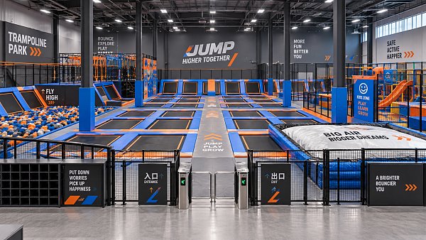
A trampoline park becomes difficult to operate when capacity, circulation, and equipment specification are designed as separate decisions. The floor may look active on an early layout drawing yet develop queues at the entry gate, crowding around foam landings, or unsafe cross-traffic once sessions begin. Custom trampoline park equipment should therefore be selected against a defined operating model: the intended guest mix, session format, supervision position, building geometry, access routes, and maintenance access all affect the final layout.
Begin with the area that can be used safely, rather than the gross lease area. Columns, fire exits, electrical rooms, ceiling obstructions, wall clearances, reception functions, party rooms, storage, and required circulation reduce the attraction footprint. A plan that fills every apparent open space with activity modules often leaves too little room for entry control, evacuation movement, or staff sightlines. The usable attraction area also needs to account for protective padding thickness, netting offsets, access gates, and the space required to enter or leave an activity without crossing an active jumping lane.
Start Capacity Planning With Simultaneous Use
Rated capacity is often misunderstood as a count of physical positions. A park may contain many trampoline beds, but not all beds support the same activity intensity or require the same separation. A free-jump court, a basketball lane, a dodgeball court, and an airbag approach have different movement patterns. Treating them as interchangeable positions can overstate the number of people who can use an area at once.
Capacity planning works better when it distinguishes between occupancy, active participation, and throughput. Occupancy is the number of people allowed inside a zone. Active participation is the number who can move at the same time without interfering with one another. Throughput reflects how many people complete an activity cycle over a session, including entry, orientation, waiting, and exit. A climbing wall beside a trampoline court can carry a different rhythm from a high-energy obstacle route, even where both occupy a similar footprint.
Use the intended session structure to test the layout. Open-jump sessions require generous circulation because guests distribute themselves unevenly. Structured classes use fewer active locations but need a clear gathering space and visible instruction point. Party groups create short bursts of demand at check-in, shoe storage, briefing, and the first attraction entered. A layout suitable for scheduled groups can become congested during general admission if these arrival waves are ignored.
Zone Capacity Is Limited by the Narrowest Condition
Each zone has a practical limit set by its most restrictive condition. That condition may be bed count, the width of a controlled entry, landing recovery time, the number of people that can be observed from a supervision point, or the clearance at a shared exit. For example, a dodgeball court may physically hold several participants, but a single gate and a narrow waiting edge can prevent safe rotation between rounds. Adding more beds does not solve the bottleneck.
Build the Layout Around Movement, Not Attraction Names
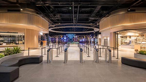
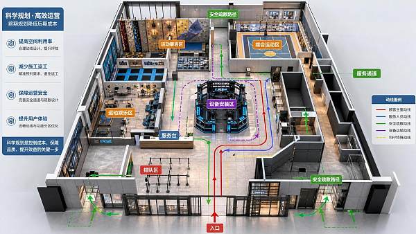
A useful plan maps a complete guest journey from entrance to exit. It should show where shoes are handled, where rules are communicated, where wristbands or session access are checked, where groups wait, and how people return from each activity. These supporting functions are operational infrastructure. When omitted from an equipment drawing, they tend to be forced into leftover space later, disrupting circulation and sightlines.
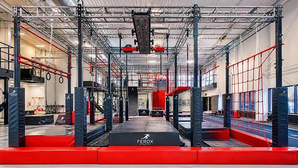
Entry and exit paths deserve particular attention around high-turnover features. An airbag, for instance, needs an approach lane that remains clear, a defined jump point, a landing area protected from entry, and an exit route that does not cross the next participant's run-up. The same principle applies to ninja-style routes and basketball attractions. A visually compact arrangement may create opposing flows at the one point where participants are moving fastest.
Place activities with similar speed and noise characteristics near one another where practical. A toddler-focused area beside a launch ramp or competitive court introduces conflicting movement expectations. Separation does not always require a solid wall. Changes in level, netted boundaries, controlled gates, padded barriers, and directional circulation can define zones while preserving visibility. However, decorative partitions should never be allowed to create blind corners.
Columns require more than a padded wrap on the final drawing. Their location changes the usable shape of courts, the tension line of netting, access to fasteners, and the path of overhead structural members. A column near a corner can sometimes be absorbed into a protected perimeter. A column inside a landing path or at the transition between two zones may force a redesign of the whole module. Record column dimensions, offsets, and height early, including protrusions concealed above suspended ceilings.
Match Equipment Structure to the Building
Commercial trampoline systems combine steel frames, springs or elastic suspension elements, trampoline beds, padding, nets, wall panels, and anchoring or ballast arrangements. Each component affects the others. A deeper frame may improve the required geometry beneath the jumping surface but increase demands on floor build-up and perimeter detailing. A taller enclosure can improve containment for certain activities while conflicting with beams, sprinkler coverage, lighting, or ductwork.
Ceiling height cannot be assessed from a single measurement at the center of the room. Measure the lowest obstruction over every proposed activity zone, then account for beam depth, suspended services, lighting fixtures, signs, smoke-control components, and the working clearance needed during installation and maintenance. Ceiling conflicts are especially common where a facility uses varied features with different vertical movement profiles. A low point that is acceptable over reception may be unsuitable over a launch-based attraction.
Floor information must be verified before fabrication. The relevant details include slab condition, finished floor level, embedded services, drainage points, expansion joints, and the load path proposed for the equipment. Surface levelness affects frame alignment; a localized high point can alter bed tension and padding fit. If anchoring is proposed, its position must be coordinated with structural drawings and any below-slab systems. A decision to avoid anchors by using a freestanding arrangement still requires confirmation that the overall structure behaves as intended under active loading.
Do not assume a flat plan produces a flat installed system. Existing floors frequently contain slopes toward drains, threshold changes, or finish layers added after base construction. Establish the reference level used for fabrication, identify tolerances that the installation method can accommodate, and decide where shimming or local floor preparation is permitted. Trying to correct substantial level differences during assembly can affect frame alignment, enclosure connections, and the appearance of padded surfaces.
Specification Details That Change Service Life
Material descriptions should be connected to the actual environment. A steel frame specification is incomplete without knowing the corrosion protection, weld finishing, connection design, and whether cut or drilled areas receive suitable treatment. In humid locations, near frequently cleaned surfaces, or where exterior air enters through loading doors, moisture exposure may be higher than the building classification suggests.
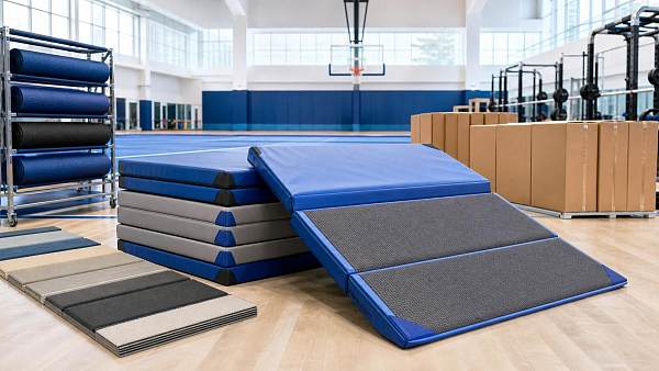
Padding is not merely a color finish. Its thickness, density, seam construction, fastening method, and cover material influence impact protection and replacement work. Loose or poorly retained padding creates trip edges and exposes hard structure. Covers around high-contact corners and entry openings face more abrasion than broad perimeter sections, so those pieces should be designed for practical replacement rather than requiring extensive dismantling. Request a clear identification system for removable pads, net panels, beds, and other wear components; this reduces confusion when replacements are ordered later.
Spring systems and elastic elements need consistent tension and secure retention. Their condition cannot be judged only from whether the bed still rebounds. Uneven response across adjacent beds, unusual noise, shifted pads, damaged connectors, or visible corrosion can indicate an issue before a complete failure occurs. Maintenance access should be built into the layout. A feature surrounded tightly by fixed décor, walls, or storage may be attractive at handover but expensive to inspect and repair.
Safety Documentation Must Follow the Installed Layout
Safety compliance is not resolved by attaching a generic certificate to a purchase order. Requirements vary by jurisdiction, building use, attraction type, and the authority reviewing the project. The equipment scope should be coordinated with applicable local rules, building approvals, emergency planning, accessibility obligations, fire protection requirements, and the relevant standards identified for the location. Where a supplier references a standard, confirm which configuration, materials, and activity use that reference actually covers.
Documentation is most useful when it corresponds to the final installation rather than a catalog image. The package should clearly identify the layout revision, structural connection approach, equipment boundaries, netting, padding, access gates, elevation requirements, and intended maintenance points. Changes made after design approval, such as shifting a court around a column or replacing a landing product, should trigger a review of adjacent clearances and operating assumptions. Small substitutions can alter more than appearance.
Sightlines deserve equal weight. A supervision position should permit a direct view of entries, active surfaces, landing areas, and likely conflict points. Mirrors or cameras may support coverage, but they do not remove the problem of a hidden corner where intervention is delayed. Raised features, branded wall finishes, netting patterns, and equipment storage can all obstruct views that appeared open on a two-dimensional plan.
Coordinate Fabrication, Delivery, and Installation Early
Custom fabrication starts with confirmed dimensions, not a preliminary concept plan. Before release, reconcile the equipment drawing with architectural, structural, mechanical, electrical, and fire-protection information. The coordination should include ceiling services, door swing and loading access, escape routes, column locations, finished floor details, and any overhead signage. A clash found after steel fabrication may require field modification that delays installation and compromises the intended finish.
Delivery planning matters because trampoline structures arrive as a large number of frames, beds, pads, springs, nets, hardware packs, and specialty components. Confirm the unloading point, truck access, internal route, lift capacity, staging space, and protection for finished floors. Components should be labeled against the approved layout, especially where several courts use similar-looking parts with different dimensions. Mixed hardware or misplaced pads can create avoidable assembly delays and make later inspections harder.
Installation sequence should preserve access to both the work area and the building systems around it. Frame assembly, bed fitting, tensioning, padding, netting, and final detailing are interdependent. Installing decorative finishes or fixed furniture too early can block the route needed to fit long frame members or access perimeter fasteners. After assembly, a documented inspection should cover alignment, connections, padding retention, bed tension consistency, net integrity, gate operation, transition edges, and the clearance of every activity path.
Design for Change Without Creating Uncontrolled Flexibility
A scalable park does not require every feature to be movable. It needs a layout that can absorb realistic operational changes: a junior zone may need to expand, a party route may need clearer separation, or a lower-performing feature may later be replaced. Preserve useful expansion edges, service access, and circulation margins where future modification is plausible. Avoid tying unrelated attractions together so tightly that changing one forces removal of several others.
At the same time, interchangeable modules should not become an excuse for unverified reconfiguration. Moving a court changes net lines, padding interfaces, access gates, sightlines, and sometimes the load arrangement. Any later alteration needs the same disciplined review applied to the original layout. The finished park should feel simple to enter and use, while the structure behind that experience remains precise: defined capacities, clear movement paths, verified building interfaces, and equipment that can be inspected without dismantling the attraction around it.
Search News
Hot Articles
- Smart Campus TechHow U.S. Schools Can Choose Laboratory Equipment for Safe, Compliant Science LabsSep 28, 2026
- Indoor PlaygroundCustom Trampoline Park Equipment: Planning Capacity, Safety, and LayoutSep 27, 2026
- Pro Stage AudioHow to Choose Dynamic Microphones for Vocals in Live Stage SettingsSep 26, 2026
Popular Tags
Need ExpertConsultation?
Connect with our specialized leisureengineering team for procurementstrategies.
Recommended News
 Sep 27, 2026Custom Trampoline Park Equipment: Planning Capacity, Safety, and LayoutCustom trampoline park equipment for safer capacity, smooth guest flow, and efficient layouts. Explore practical planning insights for a high-performing park.● Theme Park Strategist
 Aug 30, 2026Entertainment Venue Master Planning: How to Balance Capacity, Flow, and RevenueEntertainment venue development master planning: balance capacity, guest flow, and revenue with practical strategies for resilient, high-performing venues.● Theme Park Strategist
 Sep 07, 2026What Should Buyers Do When a Supplier Delivers Non-Compliant Products?What to do if a supplier delivers non-compliant commercial products: contain risks, document evidence, protect your project, and secure the right remedy.● Theme Park Strategist
 Sep 02, 2026Waterpark Capacity Management: Balancing Queue Times, Safety, and Guest ThroughputWaterpark capacity management strategies to reduce queue times, protect safety, optimize guest throughput, and build a smoother, more profitable park operation.● Theme Park Strategist
 Sep 01, 2026ASTM F2075 Explained: Testing Engineered Wood Fiber for Playground Impact SafetyASTM F2075 explained: learn how engineered wood fiber supports playground impact safety, smarter sourcing, compliance documentation, and reliable maintenance planning.● Theme Park Strategist
 Aug 24, 2026How to Evaluate an Indoor Ninja Warrior Course Supplier in Europe?indoor ninja warrior course Europe supplier guide: learn how to assess safety, EN compliance, engineering, installation, and maintenance support before you choose.● Theme Park Strategist
 Aug 20, 2026How to Choose Modular Indoor Play Equipment for Different Venue Sizes and Age GroupsModular indoor play equipment buying guide: learn how to match venue size, ceiling height, traffic flow, and age groups to create safer, smarter, and more profitable play spaces.● Theme Park Strategist
 Aug 14, 2026POB Push Lifts Overseas Pre-Registrations 45.74%POB boosts overseas pre-registrations for the 2026 China Sport Show by 45.74%, signaling stronger global buyer interest and smarter sourcing opportunities in sports manufacturing.● Theme Park Strategist
 Aug 02, 2026What to Check Before Buying Thick Gymnastic Mats Wholesale for Schools and GymsThick gymnastic mats wholesale buying guide for schools and gyms: learn how to check foam, cover durability, safety documents, samples, and true long-term value before placing a bulk order.● Theme Park Strategist
 Jul 28, 2026How to Design Inclusive Sensory Play Areas for Different Age Groups and NeedsInclusive sensory play starts with smart zoning, age planning, accessibility, and acoustics. Discover practical design tips to create safer, engaging spaces that truly work.● Theme Park Strategist
 Jul 26, 2026How to Evaluate a Bowling Alley Equipment Factory Before Requesting a QuoteBowling alley equipment factory evaluation starts before price. Learn how to check manufacturing scope, engineering, compliance, spare parts, and installation support to avoid costly sourcing mistakes.● Theme Park Strategist
 Jul 16, 2026EN 1176:2026 Takes Effect for Indoor PlaygroundsEN 1176:2026 takes effect for indoor playgrounds in the EU, making conformity assessment mandatory. Learn how this impacts certification, customs clearance, suppliers, and market access.● Theme Park Strategist
 Jul 15, 2026CPSC Sets New ASTM Impact Test for Indoor Playground Metal PartsCPSC sets new ASTM impact test rules for indoor playground metal parts effective Oct. 1, 2026. Learn how the 15kN requirement may affect compliance, testing timelines, and U.S. export delivery.● Theme Park Strategist
 Jul 14, 2026CPSC Tightens Phthalate Limit for Indoor Playground Soft MaterialsCPSC tightens phthalate limits for indoor playground soft materials from Aug 15, 2026. Learn how DIBP control, CBP detention risk, and testing changes impact sourcing, exports, and compliance.● Theme Park Strategist
 Jul 13, 2026Vietnam Tightens IoT Rule for Indoor Playground ImportsVietnam Tightens IoT Rule for Indoor Playground Imports: learn how VNSS-2025 gateway requirements affect exporters, buyers, installers, and delivery timelines before the 2026 deadline.● Theme Park Strategist
 Jul 13, 2026How a Recreational Facility Planning Company Helps Reduce Layout MistakesRecreational facility planning company insights: learn how early layout strategy reduces costly mistakes, improves flow, compliance, and buildability for smoother project delivery.● Theme Park Strategist
 Jul 12, 2026CPSC Halts Imports of Indoor Playground Soft PartsCPSC halts imports of indoor playground soft parts from China under ASTM F3432-26. Learn the compliance risks, testing requirements, and urgent steps importers must take now.● Theme Park Strategist
 Jul 11, 2026CPSC Import Alert Tightens Fire Test Rule for Indoor Playground PaddingCPSC import alert updates indoor playground padding rules to ASTM F3432-26. See how the new fire test affects foam mats, shipments, and U.S. market access.● Theme Park Strategist
 Jul 11, 2026Ice Bumper Cars Bulk Order Checklist for Indoor Parks: Space, Power, and Safety PointsIce bumper cars bulk order guide for indoor parks: learn how to assess space, power, safety, and throughput before buying, so you can avoid costly mistakes and choose the right fleet with confidence.● Theme Park Strategist
 Jul 10, 2026Commercial Playground Equipment for Campuses: Key Safety Standards and Planning TipsCommercial playground equipment for campuses: explore key safety standards, inclusive layout planning, durable materials, and smart procurement tips to avoid costly mistakes.● Theme Park Strategist
 Jul 09, 2026CPSC Recall Escalates Over Phthalates in Indoor Playground PadsCPSC recall escalates over phthalates in indoor playground pads as affected batches exceed CPSIA limits. Learn the risks, supply chain impact, and what buyers should monitor now.● Theme Park Strategist
 Jul 07, 2026How to Choose Ice Skating Rink Equipment in Europe: Key Systems, Standards, and Budget Factorsice skating rink equipment Europe guide: compare refrigeration, rink floors, boards, EU compliance, and total budget factors to choose a safer, more efficient commercial rink solution.● Theme Park Strategist
 Jul 06, 2026CPSC Flags New Flame Test for Indoor Playground PaddingCPSC flags a new flame test for indoor playground padding under ASTM F1487-23b. Learn how this urgent compliance alert affects materials, testing, imports, and U.S. market access.● Theme Park Strategist
 Jul 05, 2026Vietnam Sets VCA Registration Deadline for Indoor Playground ImportsVietnam Sets VCA Registration Deadline for Indoor Playground Imports: learn the August 15, 2026 VCA registration rule, batch EN 14960 test report requirements, and how to avoid import license delays in Vietnam.● Theme Park Strategist